Gallery & 2D views
The gallery pattern lets a single script emit everything you need to inspect a part: a shaded 3D solid, a 2D cross-section wire, Hidden Line Removal (HLR) engineering projections, and programmatic dimension annotations — all from one swift run Script invocation.
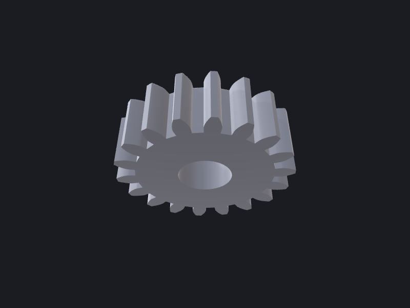
Overview of outputs
| Body ID convention | Type | Viewport rendering |
|---|---|---|
*-3d | Solid Shape | Shaded + wireframe |
profile-* or *-2d | Wire | Wireframe only |
hlr-front, hlr-top, hlr-right | Shape (edges) | Wireframe — visible lines |
hlr-front-hidden, hlr-top-hidden, hlr-right-hidden | Shape (edges) | Wireframe — dashed hidden lines |
dim-* | Shape (edges) | Dimension leader geometry |
HLR view directions
OCCTSwift uses a right-handed coordinate system. The standard engineering-drawing projections map to these direction vectors:
let front = SIMD3<Double>(0, -1,  0)          // Front view  — looks along −Y (XZ plane)
let top   = SIMD3<Double>(0,  0, -1)          // Top/plan    — looks along −Z (XY plane)
let right = SIMD3<Double>(1,  0,  0)          // Right side  — looks along +X (YZ plane)
let iso   = simd_normalize(SIMD3<Double>(1, -1, 1))  // Isometric
Diagram:
             Top (0, 0, −1)
                   ↓
          ┌────────────────┐
          │                │
Left      │     Front      │   Right
(−1,0,0)  │   (0, −1, 0)  │  (1, 0, 0)
          │                │
          └────────────────┘
Dimension types
Four dimension types are available; each returns an optional value (construction can fail if the geometry is degenerate).
| Type | Key constructors | .value units |
|---|---|---|
LengthDimension | (from:to:), (edge:), (face1:face2:) | mm |
RadiusDimension | (shape:) | mm |
DiameterDimension | (shape:) | mm |
AngleDimension | (edge1:edge2:), (first:vertex:second:), (face1:face2:) | radians |
Every dimension exposes:
.value— the measured scalar (use for console validation or manifest notes).geometry— aDimensionGeometrystruct with attachment points and text position (used by the viewport’sMeasurementOverlaysystem to render leader lines)
Runnable example
The script below builds a flanged cylinder, adds every gallery layer, and prints key dimensions. Paste it into Sources/Script/main.swift and run swift run Script.
import OCCTSwift
import ScriptHarness

let ctx = ScriptContext(metadata: ManifestMetadata(
    name: "Flanged cylinder",
    revision: "1",
    dateModified: Date(),
    tags: ["gallery", "example"]
))
let C = ScriptContext.Colors.self

// ── 1. Build the part ──────────────────────────────────────────────────────
let shaft  = Shape.cylinder(radius: 10, height: 40)!
let flange = Shape.cylinder(radius: 20, height:  5)!
let bore   = Shape.cylinder(radius:  6, height: 50)
                  .translated(by: SIMD3(0, 0, -5))

var part = shaft.union(with: flange)
if let bore { part = part.subtracting(bore) }
let part3d = part.translated(by: SIMD3(60, 0, 0))  // offset so views don't overlap

// ── 2. 3D solid ───────────────────────────────────────────────────────────
try ctx.add(part3d, id: "cylinder-3d", color: C.steel, name: "Flanged cylinder")

// ── 3. 2D cross-section wire (XZ plane, origin at base centre) ────────────
let profileWire = Wire.polygon([
    SIMD2( 6,  0), SIMD2(10,  0), SIMD2(10, 40),
    SIMD2( 6, 40), SIMD2( 6,  0)
])!
try ctx.add(profileWire, id: "profile-xsec", color: C.yellow, name: "Half-section")

// ── 4. HLR projected views ────────────────────────────────────────────────
let frontDir = SIMD3<Double>(0, -1,  0)
let topDir   = SIMD3<Double>(0,  0, -1)
let rightDir = SIMD3<Double>(1,  0,  0)

// Front view — offset below the 3D solid
if let vis = part3d.hlrEdges(direction: frontDir, category: .visibleSharp)?
                    .translated(by: SIMD3(0, 0, -60)) {
    try ctx.add(vis, id: "hlr-front", color: C.cyan, name: "Front view")
}
if let hid = part3d.hlrEdges(direction: frontDir, category: .hiddenSharp)?
                    .translated(by: SIMD3(0, 0, -60)) {
    try ctx.add(hid, id: "hlr-front-hidden", color: C.gray, name: "Front hidden")
}

// Top view — offset to the right
if let vis = part3d.hlrEdges(direction: topDir, category: .visibleSharp)?
                    .translated(by: SIMD3(60, 0, -60)) {
    try ctx.add(vis, id: "hlr-top", color: C.cyan, name: "Top view")
}
if let hid = part3d.hlrEdges(direction: topDir, category: .hiddenSharp)?
                    .translated(by: SIMD3(60, 0, -60)) {
    try ctx.add(hid, id: "hlr-top-hidden", color: C.gray, name: "Top hidden")
}

// Right-side view — offset further right
if let vis = part3d.hlrEdges(direction: rightDir, category: .visibleSharp)?
                    .translated(by: SIMD3(120, 0, -60)) {
    try ctx.add(vis, id: "hlr-right", color: C.cyan, name: "Right view")
}
if let hid = part3d.hlrEdges(direction: rightDir, category: .hiddenSharp)?
                    .translated(by: SIMD3(120, 0, -60)) {
    try ctx.add(hid, id: "hlr-right-hidden", color: C.gray, name: "Right hidden")
}

// ── 5. Programmatic dimensions ────────────────────────────────────────────
// Overall height
if let h = LengthDimension(from: SIMD3(0, 0, 0), to: SIMD3(0, 0, 40)) {
    print("Overall height : \(h.value) mm")
    // h.geometry carries attachment points for viewport overlay rendering
}

// Flange diameter
if let dia = DiameterDimension(shape: flange) {
    print("Flange diameter: \(dia.value) mm")
}

// Bore radius
if let bore3d = Shape.cylinder(radius: 6, height: 40) {
    if let r = RadiusDimension(shape: bore3d) {
        print("Bore radius    : \(r.value) mm")
    }
}

// Flange-to-shaft angle (90° shoulder)
let shaftEdges = shaft.edges()
let flangeEdges = flange.edges()
if let e1 = shaftEdges.first.map({ Shape.fromEdge($0) }) as? Shape,
   let e2 = flangeEdges.first.map({ Shape.fromEdge($0) }) as? Shape,
   let ang = AngleDimension(edge1: e1, edge2: e2) {
    print("Shoulder angle : \(ang.value * 180 / .pi)°")
}

// ── 6. Emit ───────────────────────────────────────────────────────────────
try ctx.emit(description: "Flanged cylinder — gallery pattern")
Run with:
swift run Script
The viewport auto-reloads from ~/.occtswift-scripts/output/manifest.json. You will see the 3D solid (top-left), the half-section wire (bottom-left), and the three HLR projections arranged in a row below. Console output prints the four dimension values for quick verification.
What hlrEdges returns
Shape.hlrEdges(direction:category:) returns an optional Shape containing projected edges in the plane perpendicular to direction. The shape is already in the same coordinate space as the original — translate it to a layout position before adding it to the context.
The two most-used categories:
| Category | Meaning | Convention |
|---|---|---|
.visibleSharp | Sharp edges visible from this direction | Solid line |
.hiddenSharp | Sharp edges hidden behind faces | Dashed line |
.visibleOutline | Silhouette/outline of curved surfaces | Solid line |
For approximate (faster) projection, hlrPolyEdges(direction:category:) uses polygon-based HLR and accepts the same categories.
Checklist
- Every
hlrEdgescall is optional-chained — it returnsnilon degenerate input; guard orif letbefore adding. - Separate the visible and hidden edge passes into distinct body IDs (
hlr-front/hlr-front-hidden) so the viewport can render them with different line styles. LengthDimension,RadiusDimension,DiameterDimension, andAngleDimensionare all failable — unwrap before using.valueor.geometry..geometryis for viewport overlay rendering; for console validation,.valueis enough.- Use the
*-3d/profile-*/hlr-*/hlr-*-hiddenID conventions so the viewport and any downstream tooling can categorise bodies without inspecting geometry.